This is an old version of this page, you are now being redirected to the new one:
< a href="https://www.fabsurplus.com/blog/refurbishing-nikon-stepper-sdi-success-story/">https://www.fabsurplus.com/blog/refurbishing-nikon-stepper-sdi-success-story/
This was achieved via a Sharp air conditioner/heat pump model AY-XP-18GR of capacity 5.0 kW in cooling and 5.7 kW in heating. Maximum power consumption is 2.8 KW. To avoid heat generation, the cleanroom is lit using exclusively fluorescent lamps.
This was achieved using a total of 16 filter fan units mounted in a cleanroom area of 20 square meters.
The frame of the cleanroom was constructed in steel with plexiglass panels screwed onto the steel frame and glued in place with low particle production silicon sealant.
The floor is covered with anti-static cleanroom tiling with an earthed grid running under the floor, with 2 earthing points to prevent the buildup of electrical charges within the cleanroom structure.
The chase area is separated from the clean area at a height of 70 cm. The gowning area is situated in front of the entrance door and includes a further two filters to provide a laminar flow during gowning.
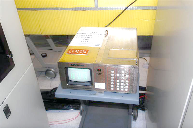
Measurements with a PMS Lasair 110 (see picture on the right) showed that the cleanroom was at class 10 level.
During operation at class 10 levels, personnel wear cleanroom clothing consisting of a full body cleanroom suit, a mutex hood, face mask, plastic overshoes and gloves.
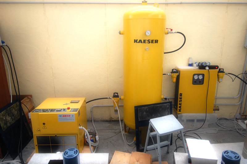
We achieved this via a Kaeser SX6 4KW screw compressor, a reservoir, a Kaeser model DC5.8 dryer, and a series of 3 particle filters.
The compressor has a maximum 9 bar operating pressure. The reservoir is of capacity 500 litres. There is a filter type Kaiser ZK01 between the screw compressor and the 500 litre reservoir. There is an Kaiser Ecodty 21 plus filter unit on the air outlet of the reservoir.
At the outlet of the air dryer are mounted 2 air particle filters, Kaiser FC10 and FFG10.
In order to provide vacuum to the equipment, an Edwards E2M40 oil rotary backing pump was used.
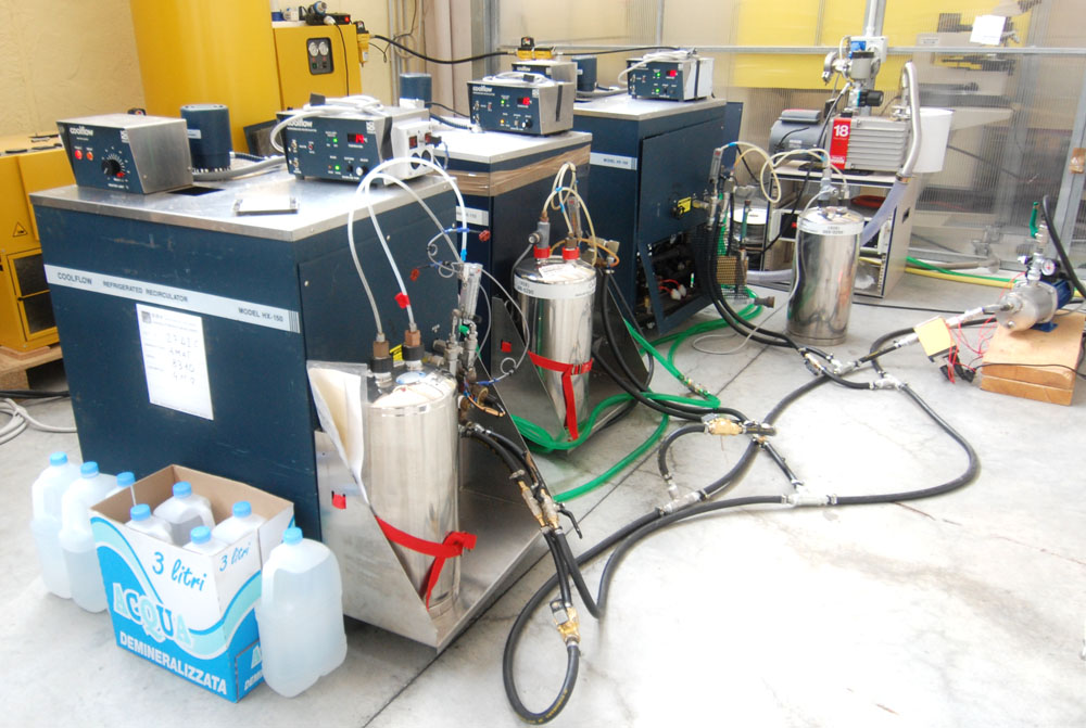
As the stepper requires 18 l/min cooling water at 21° Celsius,
we investigated different options.
Our initial plan was to use Neslab chillers.
However, it was discovered that the pumping capacity of the chillers was insufficient to generate the required pressure at the machine water inlet.
The pressure and the flow were monitored, and
we connected 3 Neslab HX150 units in parallel.
This produced a flow of about 10 l/ min at 2-3 bar inlet pressure, which was not sufficient.
We then connected an electric wafer pump of capacity 20-70 l/min and power consumption 3.75 kW on the inlet line.
We fitted the pump with a safety cutout system to avoid damage to the pump in the case that water supply was interrupted.
The atmospheric pressure reservoirs of the Neslab HX 150 chillers were connected using tubing of 50 mm diameter so as to allow any flow imbalances to be obviated.
The above system was able to supply to the machine in operation a flow of around
20-22 litres/minute of cooling water at a temperature of circa
18° Celsius at the ingress.
The supply was at a pressure reaching peaks of 5 bar. The internal diameter of the tube to supply the machine was 12 mm.
It would be possible, and desirable, to increase the flow and reduce the required inlet pressure by increasing the diameter of the water supply pipe to an ID of 20-30 mm.
We measured the water flow rate using a Kobold DFWMA water flow meter.
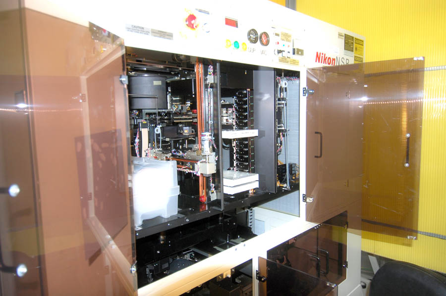
After the stepper had been positioned in the cleanroom, we levelled the
system, and connected the facility supplies, checking their
correct functioning.
We re-charged the refrigerant and checked the beam delivery optics,
together with the alignment system. We then overhauled the stage
and we run a stage drive test to test accuracy. The power of the lamp transmitted to the wafer surface was verified.
We exposed pre-coated wafers using the Nikon test reticle, and
regulated focus.
We then manually developed the exposed wafers in a photoresist developer bath.
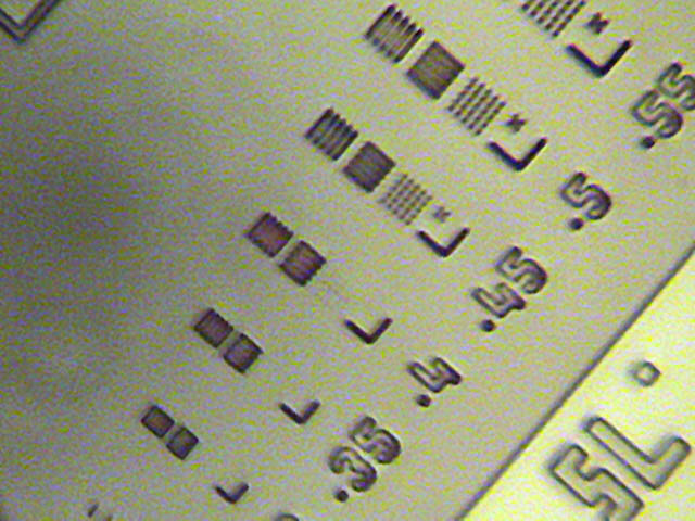
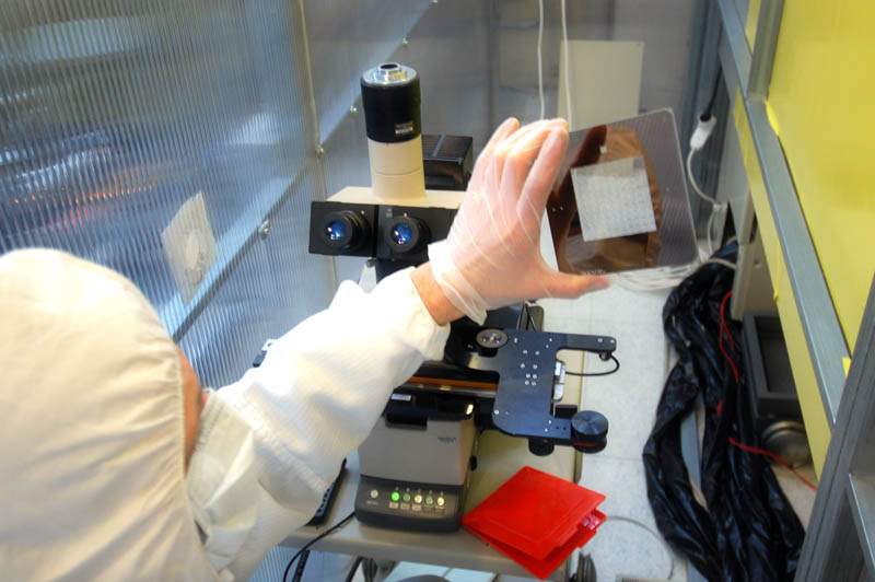
The wafers were observed using an Olympus BHMJL inspection microscope, with a maximum 50X magnification.
A Sony digital camera with 3x optical and 10x digital zoom was mounted on the microscope and photos of the wafer showing a resolution of better than 0.45 um were obtained by illuminating the wafer with a 100 watt 12 V light source.
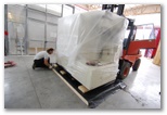
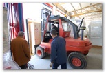
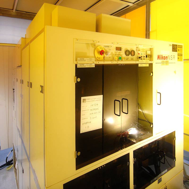
Here you can see photo galleries related to the crating and loading the Nikon Stepper.