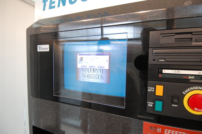
Based on the 20 year experience of our staff members, SDI-Fabsurplus has been developing the capability to support and refurbish KLA-Tencor wafer inspection , particle detection and metrology systems and install them to OEM specifications.
Since September 2011, Fabsurplus.com has further expanded it’s technical support capabilities by appointment of a lead KLA support engineer. SDI-Fabsurplus is therefore now happy to quote for refurbishment, programmed maintenance, service interventions, laser changes, training and matching worldwide on surface scan wafer particle detection products.
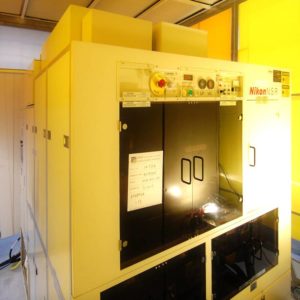
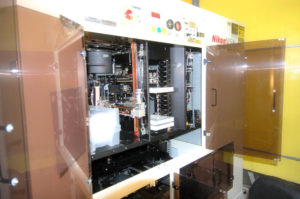
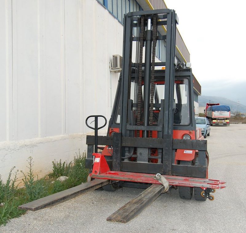
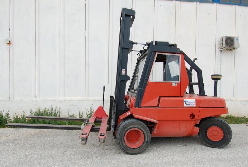
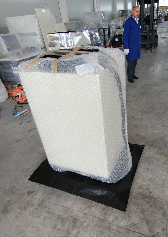
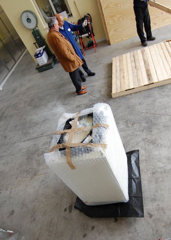
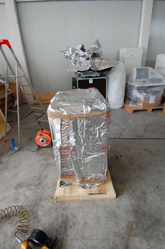
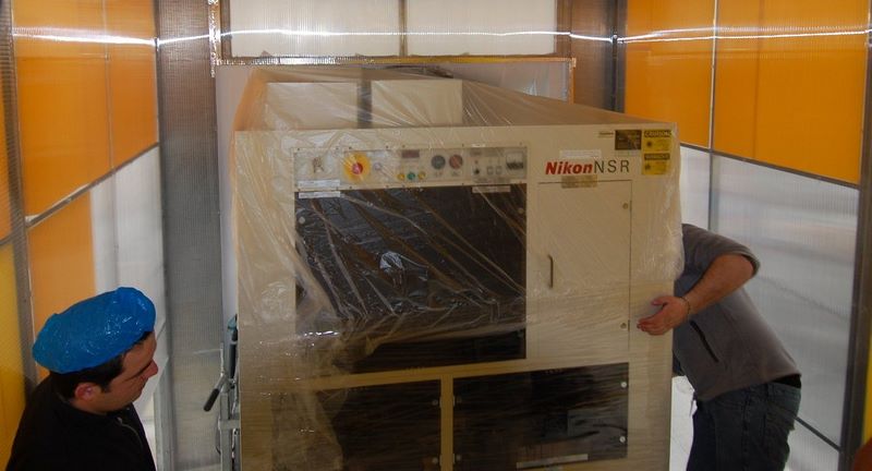
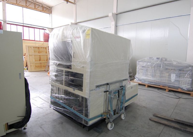
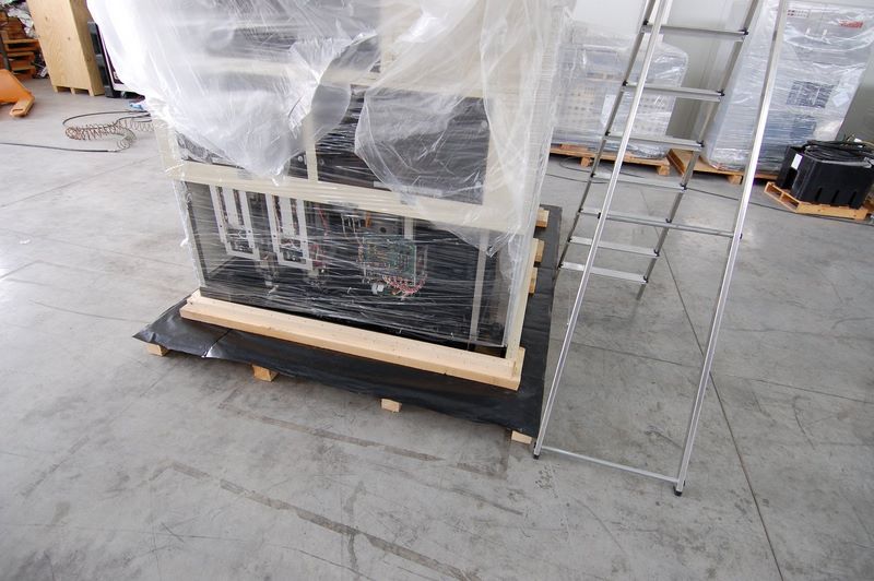
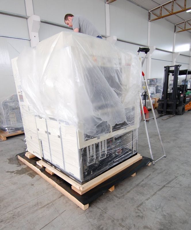
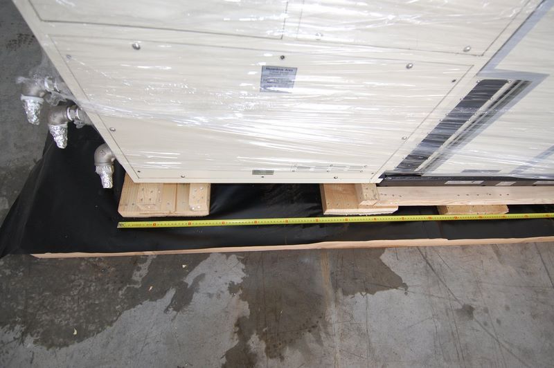
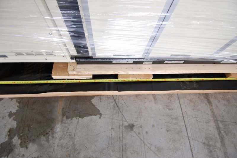
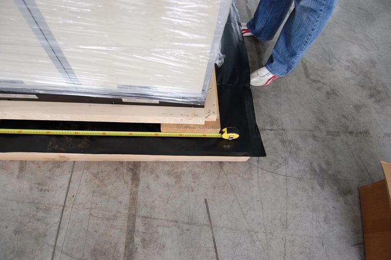
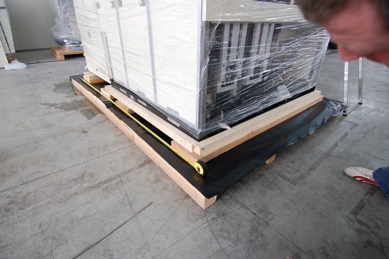
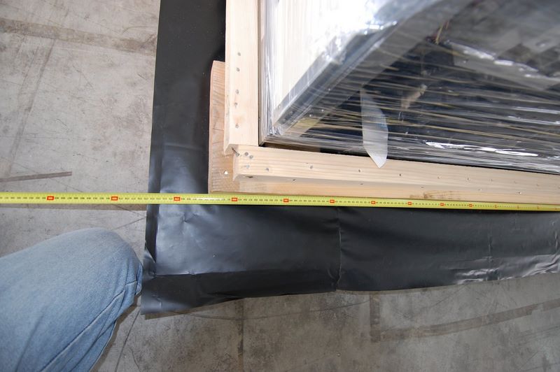
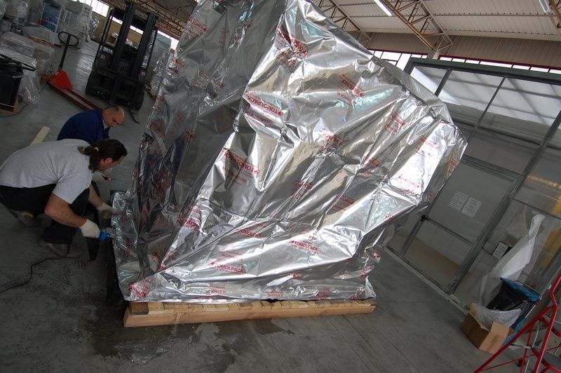
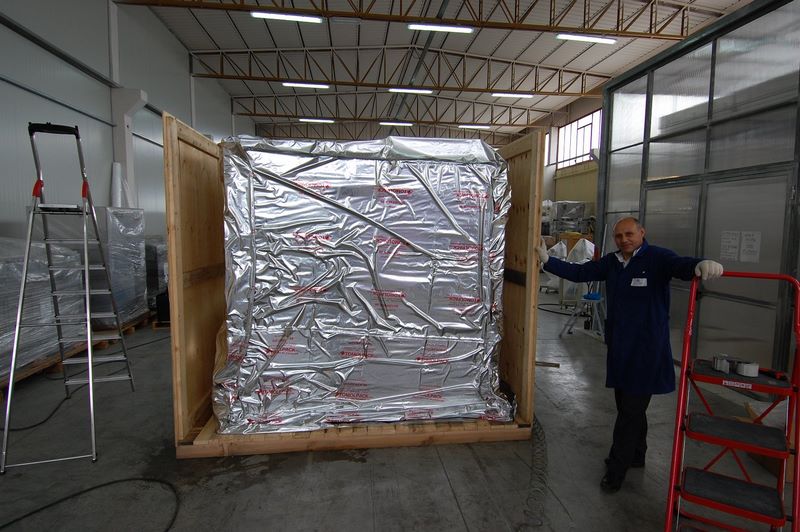
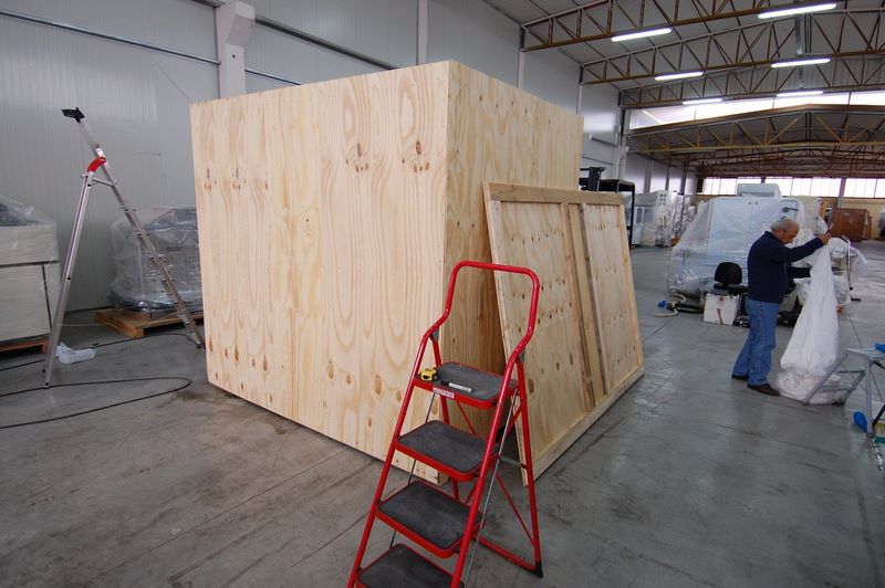
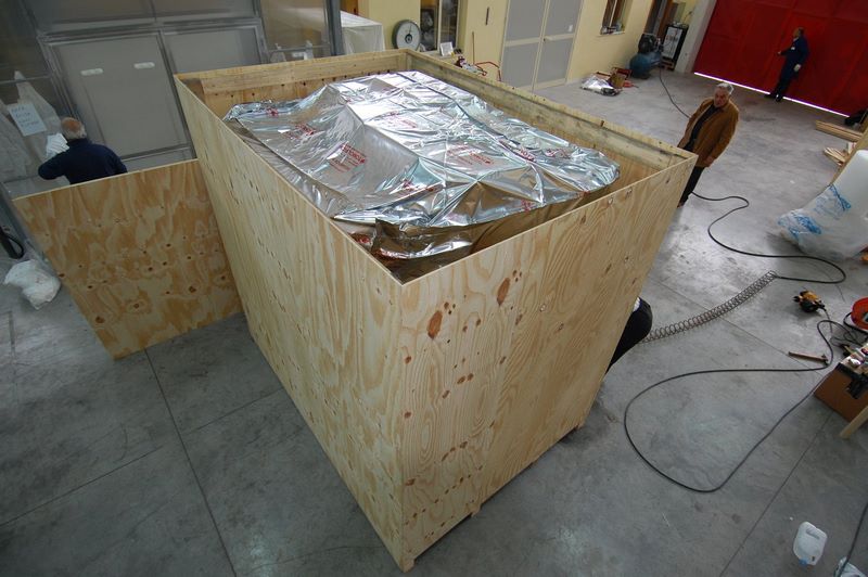
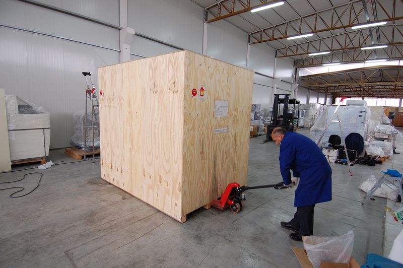
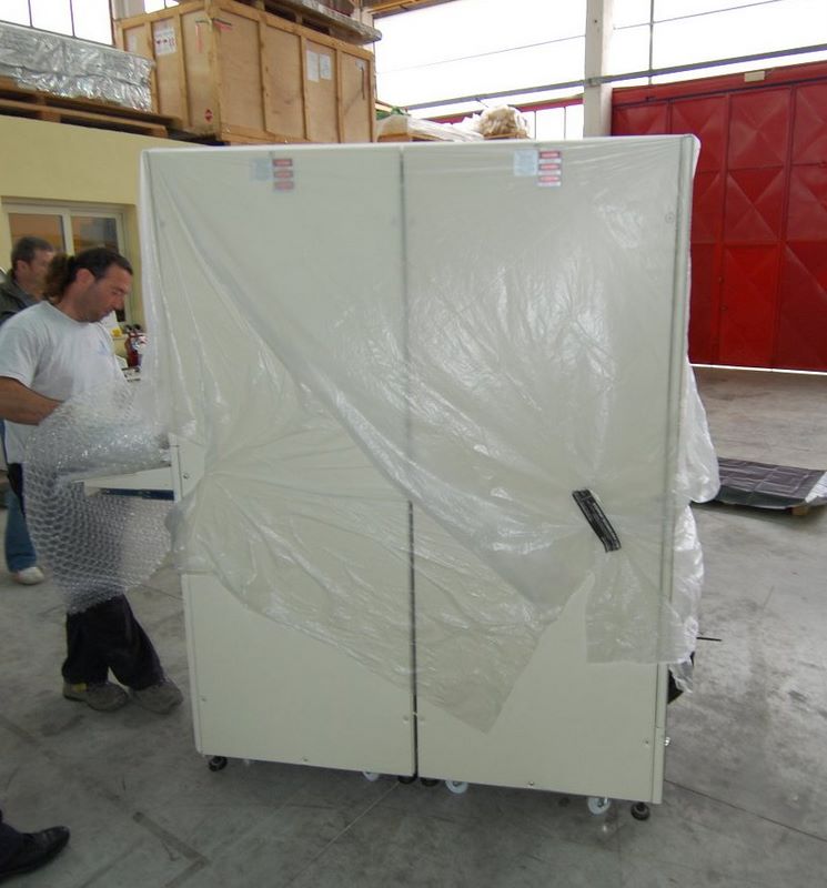
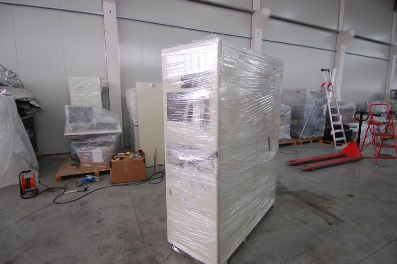
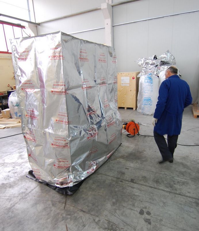
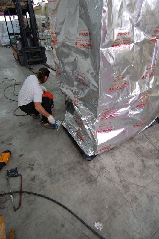
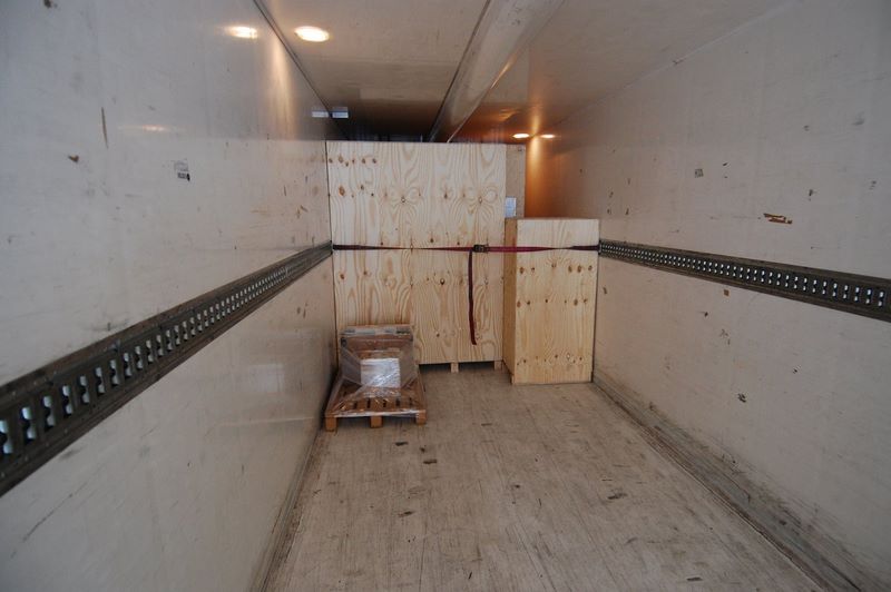
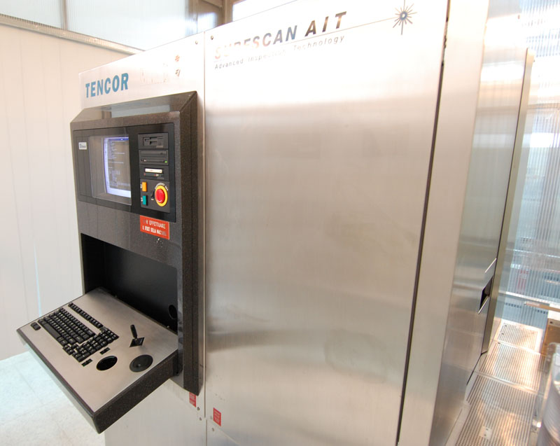
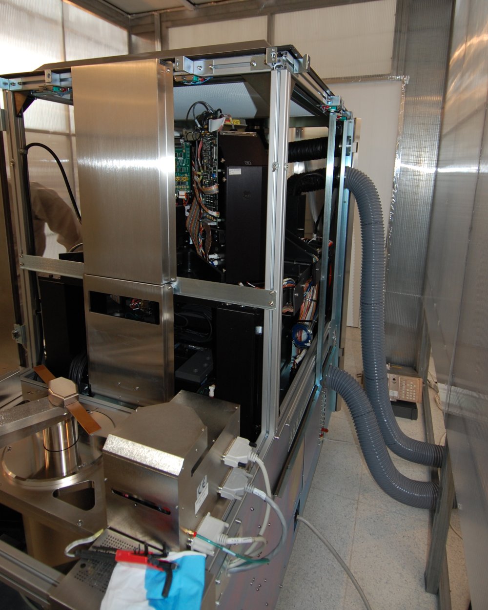
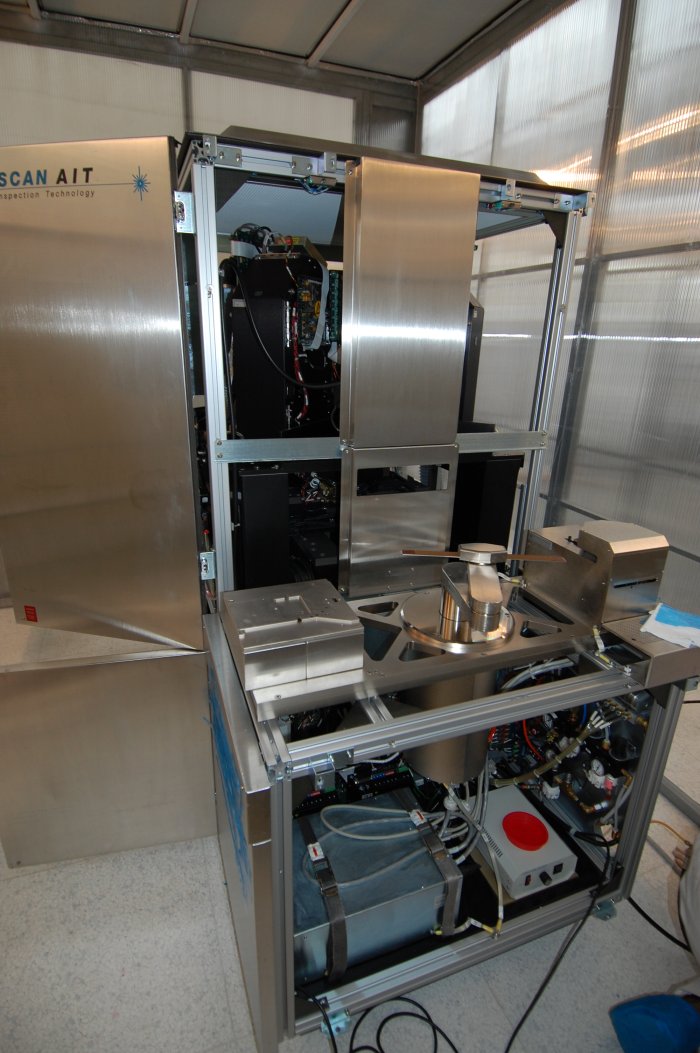
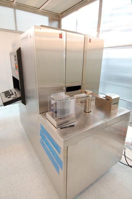
Example Project: Refurbishment and Turnkey Installation of a KLA AIT particle detection system
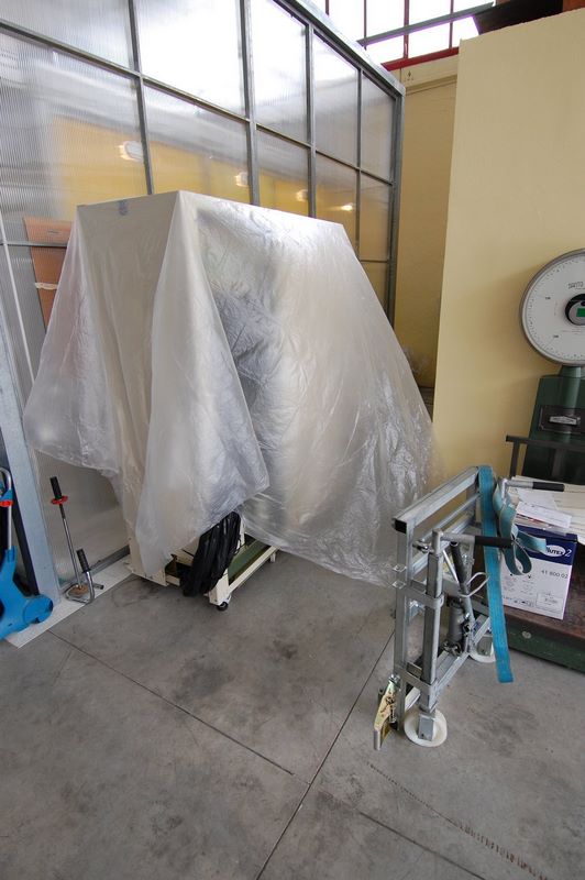
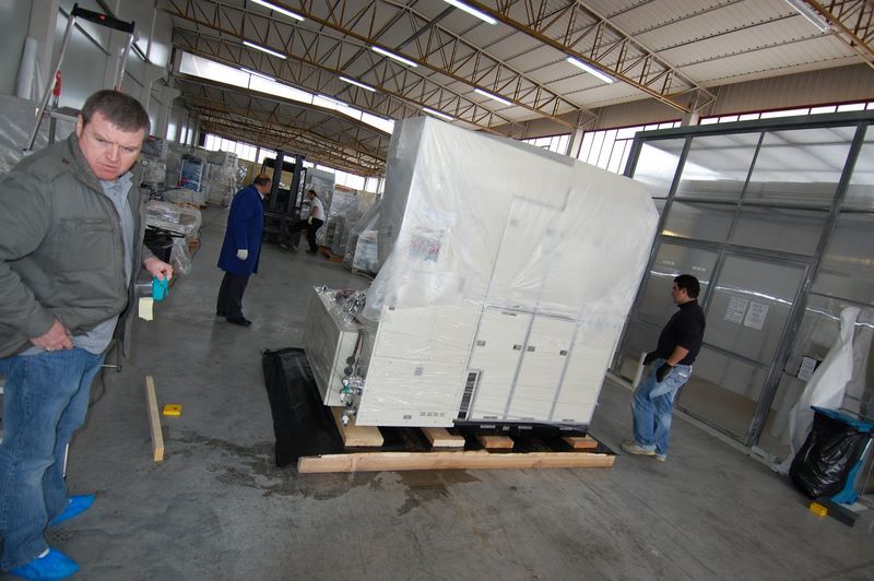
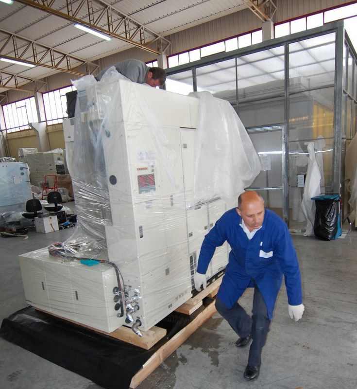
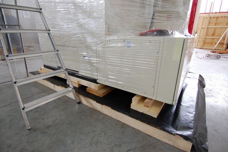
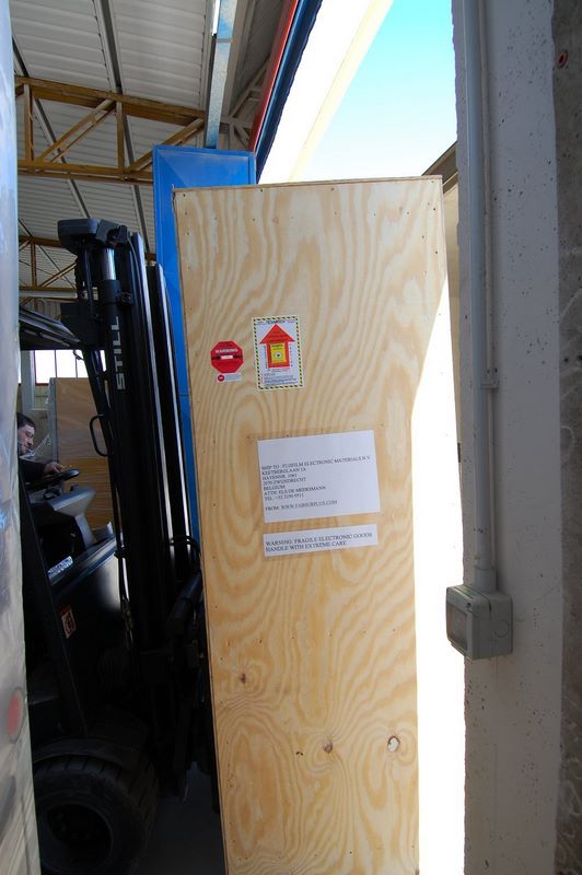
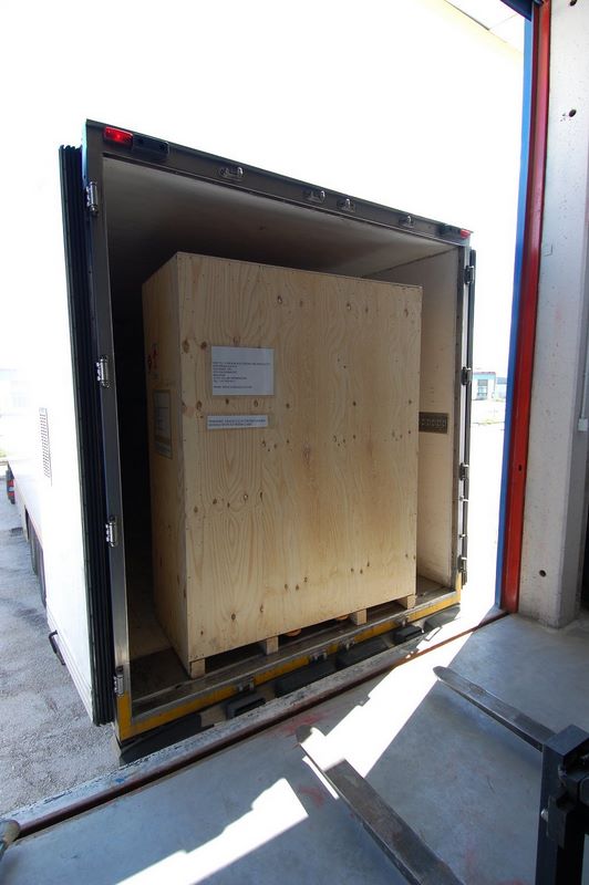
An example of a successful KLA Surfscan refurbishment project was the consignment to our client
of a KLA AIT wafer surface particle inspection system.
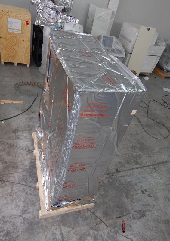
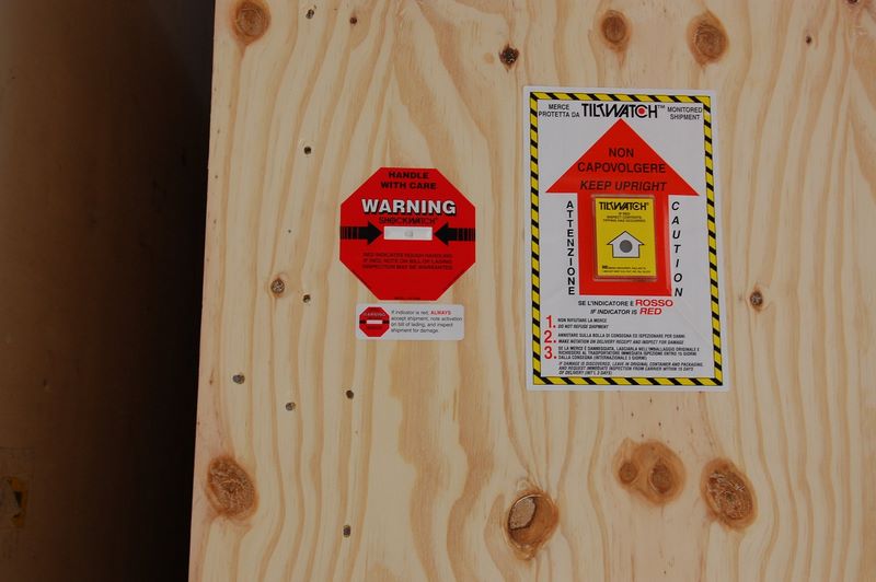
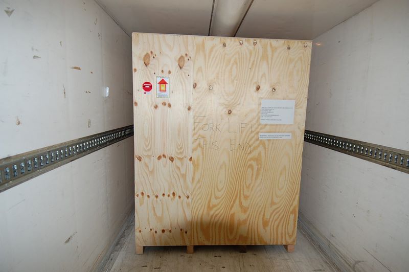
The system was completely refurbished at our Avezzano, Italy refurbishment centre, the functionality to OEM specifications was checked and then the system was consigned to our client and installed and tested on site.
Required Environment
Due to the sensitivity of KLA systems to changes in environmental conditions and particle levels, a key to our success has
been establishing a clean facility where we have control over the environmental factors in our error budget during system
refurbishment.
This allows us to concentrate on optimising performance of the system to and beyond OEM specifications,
and will give us leeway in performance to allow for any unexpected problems we might encounter on site during system install.
In order to succeed putting into the best working environment conditions the KLA AIT,
the following were the required
actions to be taken:
AIT1 SYSTEM FACILITIES
1. Air Pressure, facility requirement
The facility supply pressure to the system inlet regulator must be a minimum
of 85 PSI @ maximum flow rate of 4 SCFM and not exceed 105 PSI @ 0 SCFM.
The CDA/N2 must be dry to -20 degrees Fahrenheit and filtered to 0.1 microns.
2. Vacuum requirement
The system vacuum must greater than 20” (Hg) @ 0.5 CFM at the TECO panel inlet of the system.
3. Venting
a)Blower Exhaust
Blower A, Laser exhaust
75 CFM, discharging at 2100 BTU per hr./ 5 mw (standby)
CFM, discharging at 2800 BTU per hr./ 10 mw
CFM, discharging at 3500 BTU per hr./ 30 mw
Blower B, System exhaust
105 CFM, charging 4000 BTU per hr. at all Laser powers
b)Purge (Particle collector)
Approximately 5” Hg of vacuum at the facility outlet regulator
4. Vibration, Floor
Refer to Preinstallation Guide, Tencor P/N 348325
5. Environmental requirements
Temperature: 66 to 70 Fahrenheit,
Humidity: Standard Fabrication environment (> 30%)
Air Quality: Federal Standard 209 Class 10 or cleaner environment
6. AC power requirements
Power: Europe 220 VAC +/- 10% 30 A 50 Hz
Meeting the requirements
Stabilized temperature
This was achieved via a Sharp air conditioner/heat pump model AY-XP-18GR of capacity 5.0 kW in cooling and
5.7 kW in heating.
Maximum power consumption is 2.8 KW.
To avoid heat generation, the cleanroom is lit using exclusively fluorescent lamps.
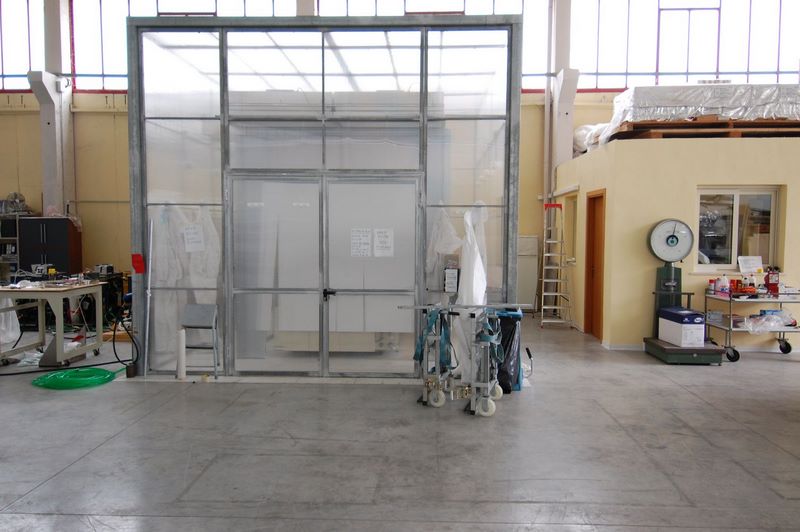
A class 10 cleanroom
This was achieved using a total of 16 filter fan units mounted in a cleanroom area of 20 square meters.
The frame of the cleanroom was constructed in steel with plexiglass panels screwed onto the steel frame
and glued in place with low particle production silicon sealant.
The floor is covered with anti-static cleanroom tiling with an earthed grid running under the floor, with
2 earthing points to prevent the buildup of electrical charges within the cleanroom structure.
The chase area is separated from the clean area at a height of 70 cm. The gowning area is situated in front
of the entrance door and includes a further two filters to provide a laminar flow during gowning.
Measurements with a PMS Lasair 110 showed that the cleanroom was at class 10 level.
During operation at class 10 levels, personnel wear cleanroom clothing consisting of a full body cleanroom
suit, a mutex hood, face mask, plastic overshoes and gloves.
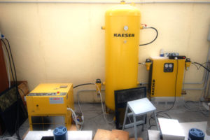
Supplying clean, particle free dry air
We achieved this via a Kaeser SX6 4KW screw compressor, a reservoir, a Kaeser model DC5.8 dryer, and a
series of 3 particle filters.
The compressor has a maximum 9 bar operating pressure.
The reservoir is of capacity 500 litres.
There is a filter type Kaiser ZK01 between the screw compressor and the 500 litre reservoir.
There is an Kaiser Ecodry 21 plus filter unit on the air outlet of the reservoir.
At the outlet of the air dryer are mounted 2 air particle filters, Kaiser FC10 and FFG10.
Creating Vacuum
In order to provide vacuum to the equipment, an Edwards E2M40 oil rotary backing pump was used.
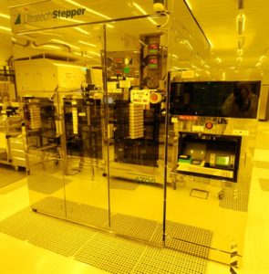
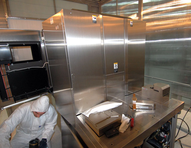
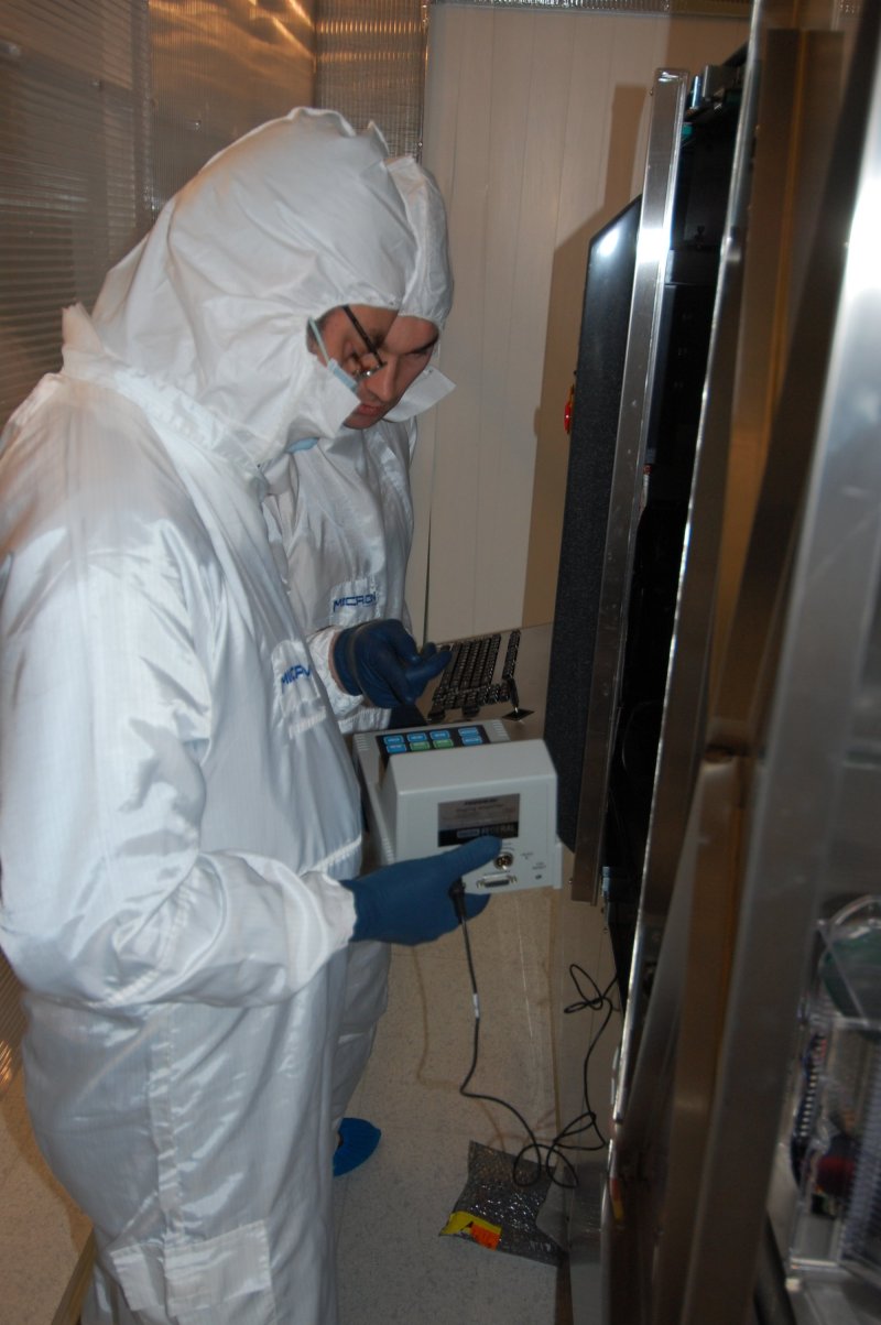
Starting up the system
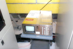
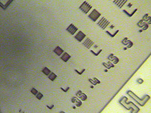
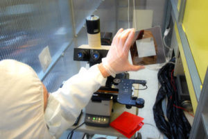
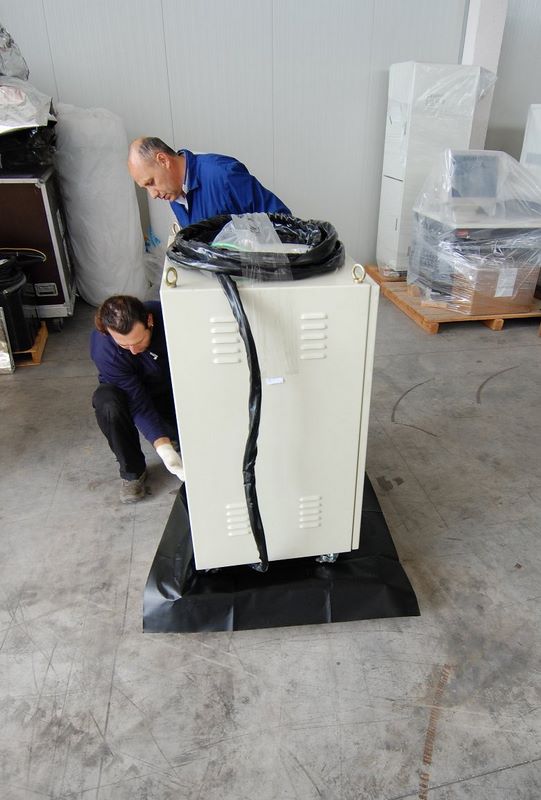
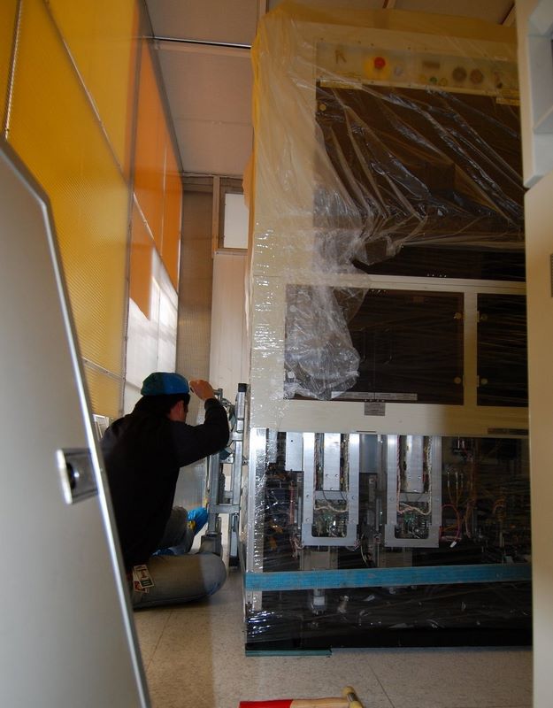
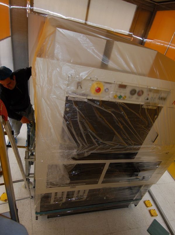
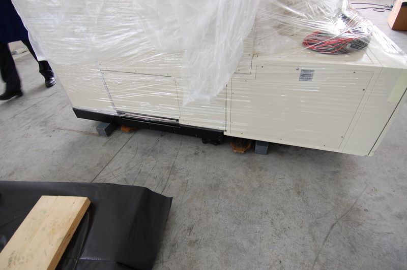
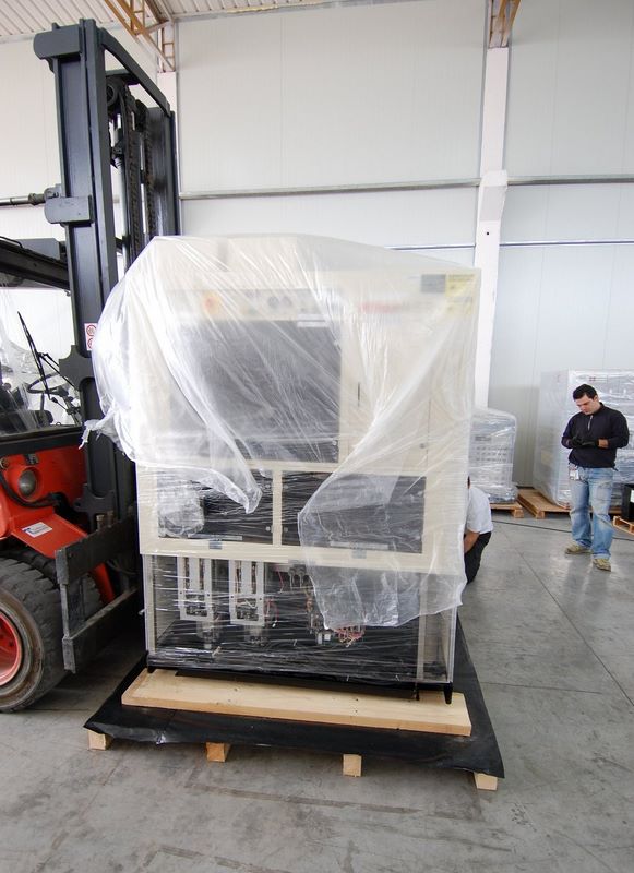
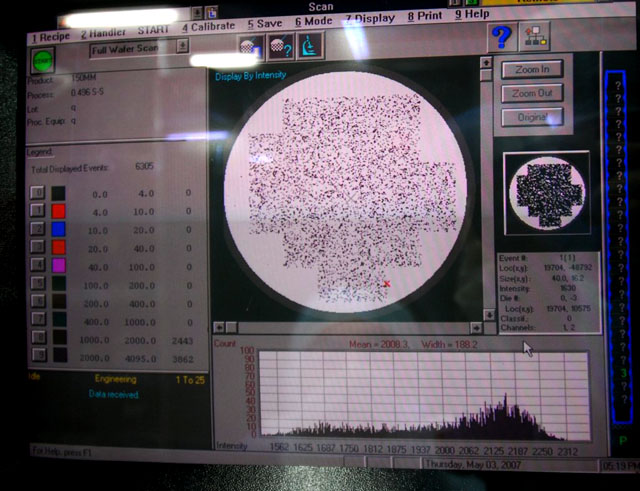
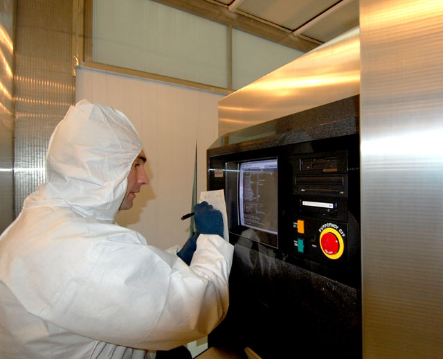
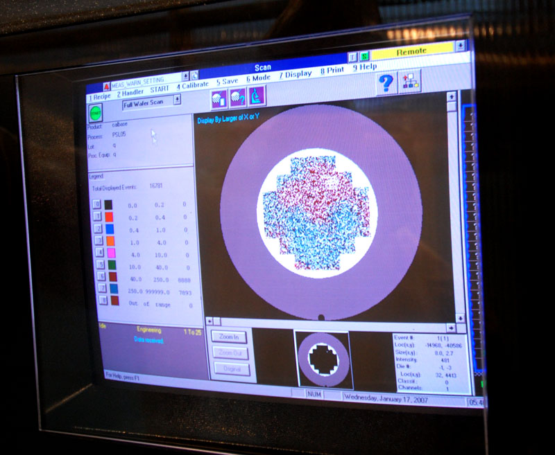
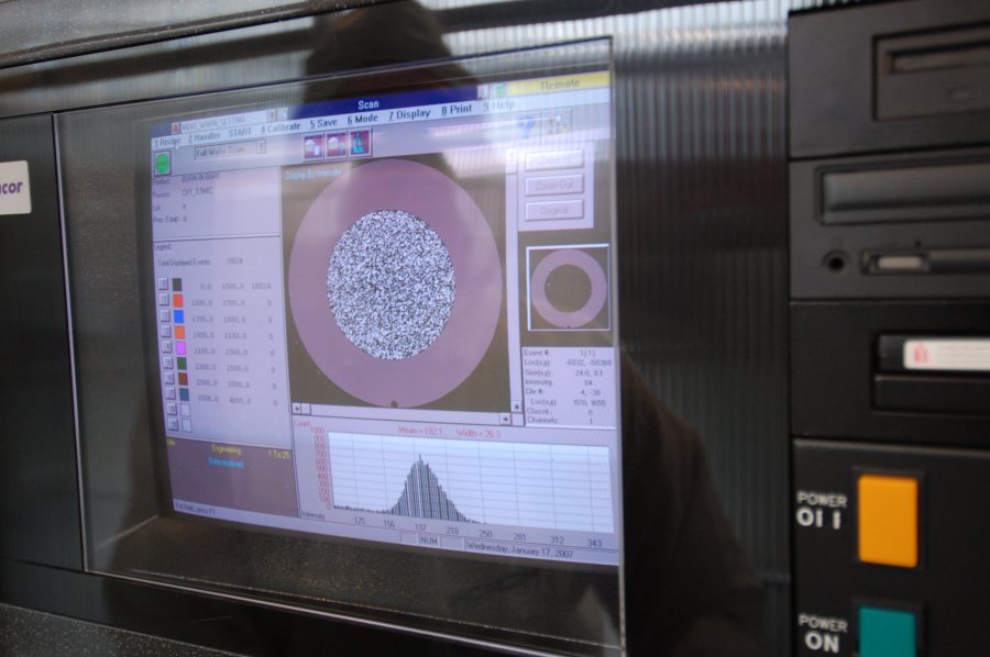
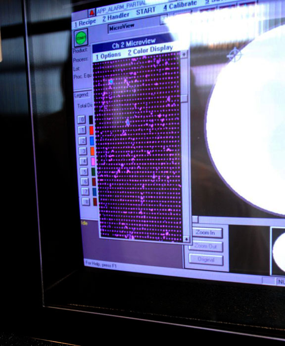
After the AIT had been positioned in the cleanroom, the system was powered up and the performance was checked.
It was observed that the PMTs needed replacing and the Laser needed replacing.
The PMTs and laser were replaced and aligned.
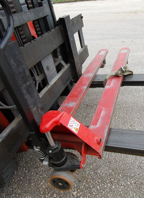
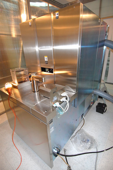
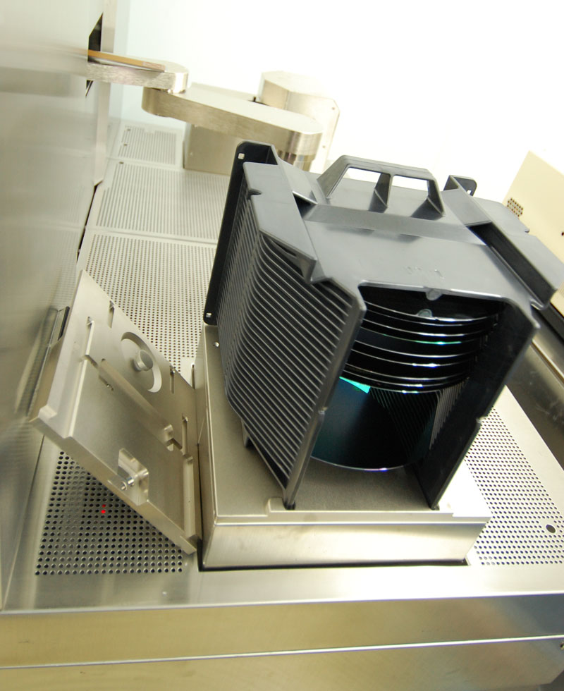
The customer required to use the system with 6 inch wafers.
A new 6 inch chuck was manufactured and the stage was re-levelled,
so as 6 inch wafer performance could be checked.
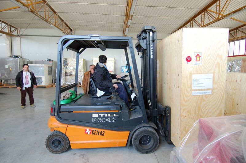
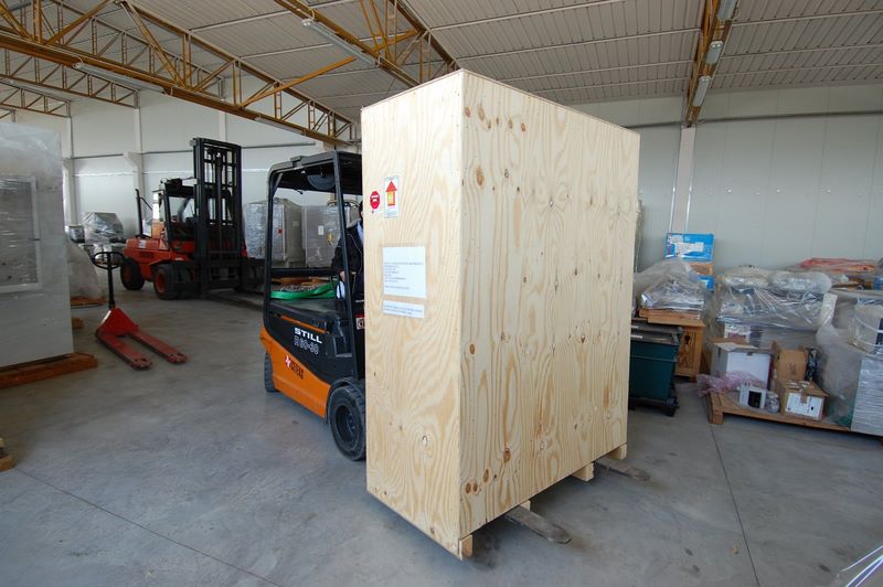
All OEM performance specifications were achieved and then the system was shipped to the client.
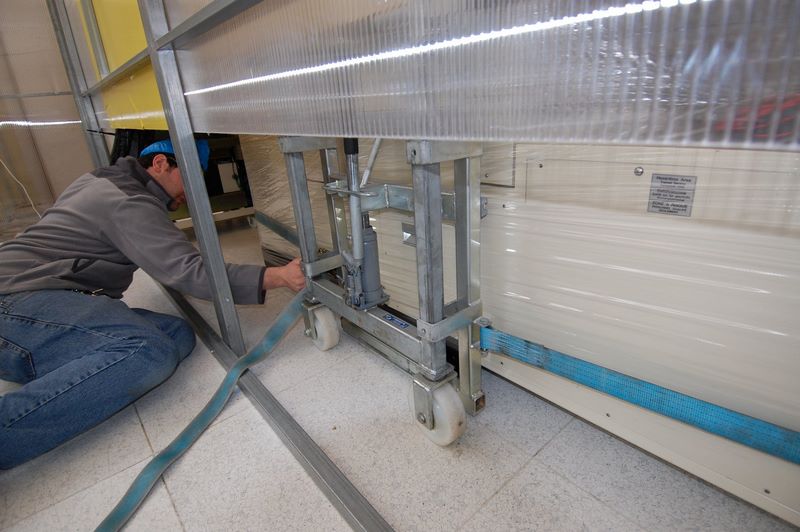
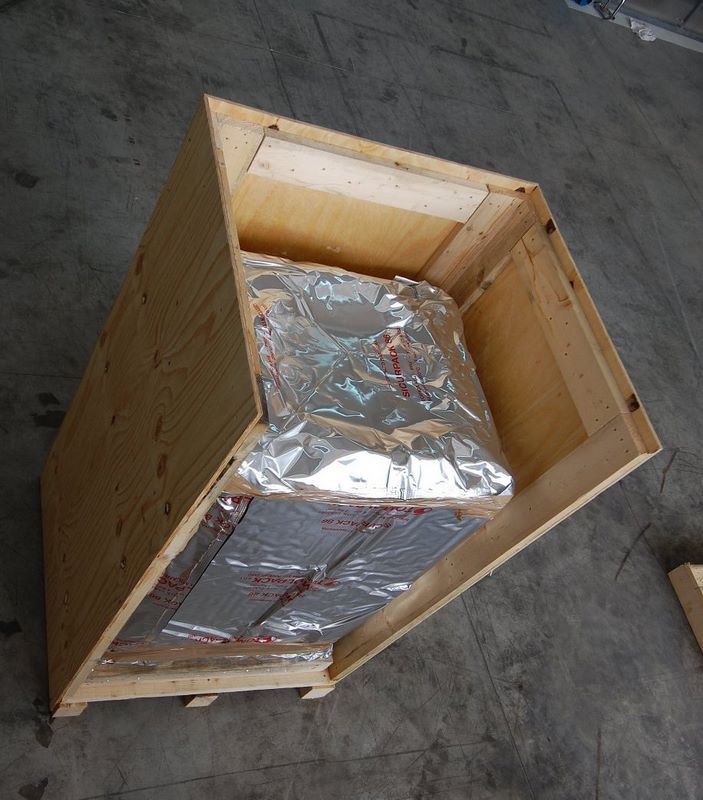
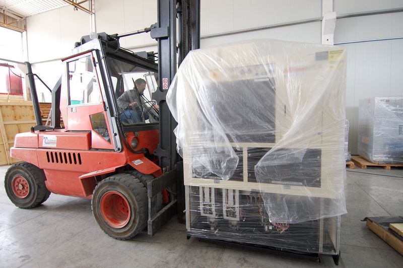
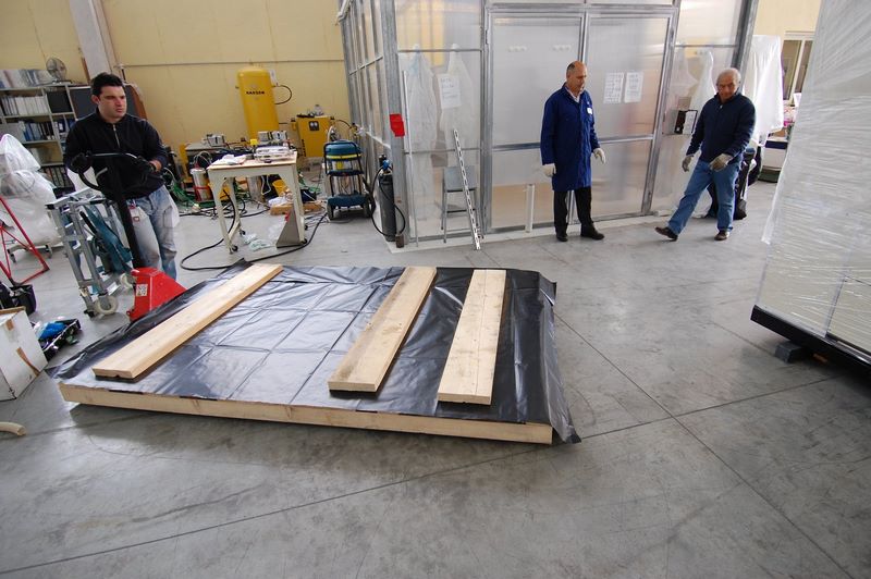
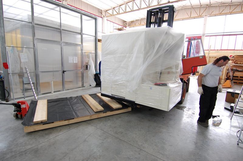
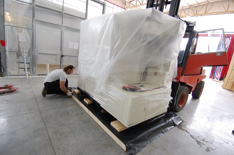
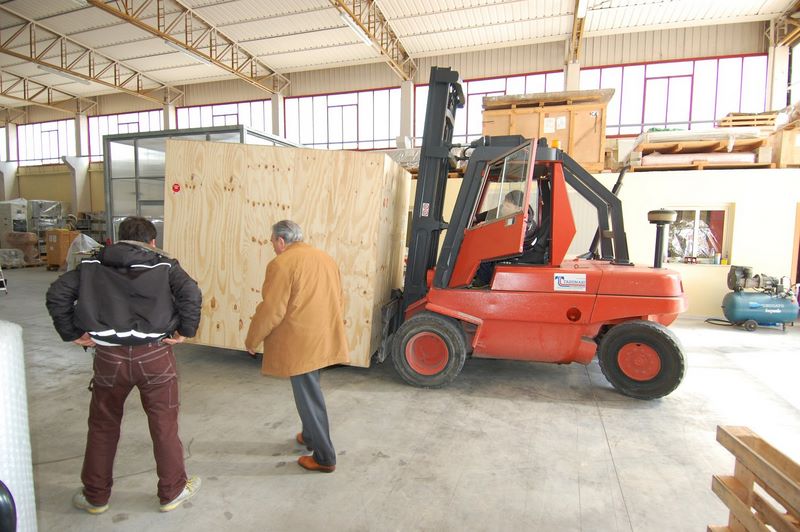
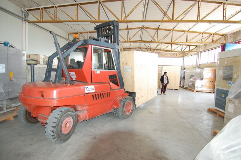
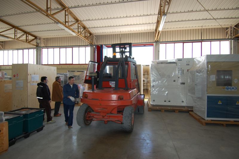
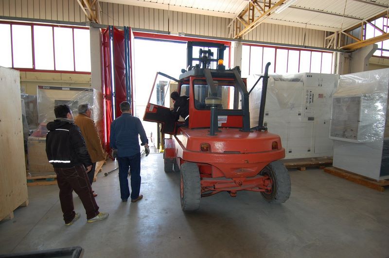
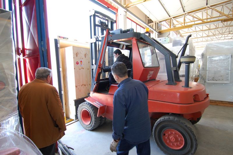
Installation of the system
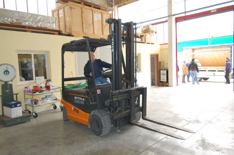
The system was positioned by customer move-in team on the pedestal.
The system was set up again by SDI engineers and consigned to the customer.
Total install time was less than the 14 days programmed.
Conclusion
SDI was able to consign and install a KLA AIT system at our clients fab
for a fraction of the cost of a newer tool from the OEM.
The customer was able to purchase the tool from his maintenance budget during a spending freeze on new capital equipment.
He did not require the performance of the newer KLA tools, as his product was typically at the 0.5 um technology node.
Buy and sell KLA-Tencor refursbished equipment with fabsurplus.com
SDI’s aim is to help our customers properly and efficiently purchase, use and re-use semiconductor manufacturing equipment,
saving money for the buyer and the seller.
SDI can supply a range of refurbished KLA tools installed and guaranteed functional to OEM specifications,
from Brightfield inspection tools, laser surface inspection tools, reticle inspection tools to CD SEMS and surface profilometers.
| Click here for a list of available KLA equipment at SDI fabsurplus.com (also Tencor and Prometrix) |
| Reticle Defect Inspection
Brightfield wafer defect inspection
Ellipsometer
Dektak
Profilometer
Macro Defect Inspection
Darkfield wafer defect inspection |
Scanning Electron Beam Microscopes
Resistivity Measurement
4 Point Probe
Cv Measurement
Carrier Lifetime Measurement
Surface Particle Detection Equipment |
Overlay Measurement Equipment
Emmi
Stress Measurement |